Header Assembly for Revit Structure…..next step prepare an extension that does complete design!
16 Mar 2011 Leave a comment
in Revit, Structural Engineering, Technology, Wood Structures
Below you will see the header assembly I created for revit structure. You can do following things with it…
1. Customize opening width
2. Customize opening height
3. customize number of jack studs
4. customize number of king studs
5. customize header depth
6. customize header width (will change automatically with wall thickness)
7. Jacks and King studs depth will change automatically with wall thickness
8. You can insert at any level and customize its offset from level
Solar Panel and it’s effects on design!
06 Mar 2011 Leave a comment
in Structural Engineering, Technology Tags: energy savings, environmental friendly design, solar panels, structural engineering for solar panel
Solar panels are now becoming popular with energy savings and environmental aspects. Most of the time the solar panel installation experts are available from manufacturing companies and are familiar with most of the structural problems and they already have attachment details on how to connect solar panels with roof.
Solar panels are not too heavy in weight, at the most they may be around 35 lbs in weight maximum which can hardly add a load of 3 psf on roofs in addition to snow and roof dead loads. Most of the roofs are designed with heavier ground snow loads such as 30 psf or 35 psf in northern regions where the there are more blizzards and lots of snow. Comparing this with weight of solar panels the gravity load is not big of a difference, and most of the roof trusses and rafters are capable to rest this load. However, the issue may become critical from design point of view when we think about uplift.
The uplift from wind may become more critical rather than gravity load itself on solar panel. Depending on size of solar panels it may induce larger uplift loads on rafters/roof trusses depending on which region its being used. In higher wind region it may cause greatest uplifts on roof rafters/trusses which may require to review connection detail/typical design for connection provided by solar panel manufacturer. Experts at solar panel providers have tested worst case scenarios but it also advisable to coordinate with them on any project specific issues that may cause review of typical connection detail. Sometimes due to high winds it may become necessary to deign bolted connections to attach solar panels to roof rafters/trusses.
From my experience in dealing with solar panels so far is, the attachment was with (3) 12d nails to 2×6 blocking to top chord of trusses wither toe nailed or face nailed and then the bracket to solar panel is attached to 2×6 flat members. Also, interesting aspect is, solar panels are not possible with slopes less than 2:12 or greater than 6:12. I would like to see comments if someone can confirm or argue this. This is from my experience with specific type of solar panels.
(the above article is based on various readings and experience that is faced with recent design and shall not be treated as professional advise. Architect/Engineer or solar panel experts are responsible for their design and the final decision)
Material Properties in Revit Structure!!!
23 Jan 2011 Leave a comment
in Revit, Technology, Wood Structures Tags: all about revit, How to change material properties revit structure, Revit Structure, Revit Structure Material Properties, step by step revit
Many times when we download Revit Libraries from online resources we do not find the right material that we need. In order to have the right material properties selected you can follow below procedures.
1. Open the .rfa (Family) file
2. Go to Manage >> Material tab from menu bar
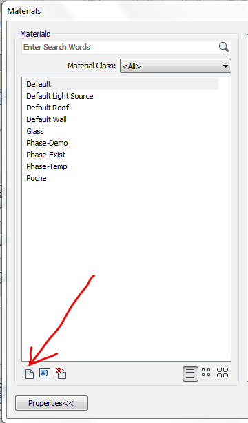
3. Click on Material will open below window >> Add New Material (See very bottom left)
4. By clicking this icon it will ask you to duplicate material >> Click OK >>
5. Now…Look at right side of new window >>you will need to set up Material properties such as Graphic >> As shown below…
6. In Graphics Tab >> chose the material color (RGB code) or chose color from pallet. You can also select surface pattern.
7. Now we will select rendering of material…in this example its for wood material (Make sure to keep the same for entire library)…Please note that the RGB code for rendering may be different than your regular graphics RGB Code.
8. Now we will create identity of material….which is in our case>>>wood so it will not have manufacturer specific identity which may be the case in order to create manufacturer specific material properties.
8. Now we will add Physical properties, now this is very important in case of Revit Structure because if we want to incorporate in to any structural analysis software these properties may be transferred to the analysis program and hence modeling need to be done only once.
9. Hit Apply>>>OK. You are all set with your new material. Select elements of the revit family and apply this material.
The world is changing an Engineer has to be a “Reviteer” now !!! Go Revit Structure !!
19 Jan 2011 Leave a comment
in Revit, Structural Engineering
 As the world is moving forward and technology is changing drastically which makes our life easier but at the same time requires great deal of knowledge in dealing with new technology. One of it is Revit, which I am working on since many years but with 2011 version it has given me everything that I need. Yes….it was behind for structural engineers than architects but its almost there now. We can do almost anything we want with Revit Structure. Model Concrete, Steel or wood structure. Here is one of the samples I am preparing for wood structure…its just an exercise and experiment towards excellence. Nothing related to any particular project but just a pure “Research work”. Will keep updating as I move on. Here is one of the model I am preparing with framed walkout basement and concrete foundation wall with I joist framing. I am not sure if architecturally how efficient the plan will be, but I have pretty good idea of what I am modelling structurally and what I am planning to test and once its done should be a good example with details and everything.
Design of structures for lateral loads
17 Jan 2011 Leave a comment
There are three methods to figure out wind loads for structure by wind loads
1. Simplified Procedure ( height < 30 ft, Slope < 10 degrees)
2. Analytic Procedure
This includes Main Wind Force Resisting System ( MWFRS) in which the wind loads are applied to structure from more than one direction while on Component & Cladding, wind load is being applied to cladding and then transferred to structural components
3. Wind Tunnel
This method is useful to analyze complex conditions, such as Y, L or T shaped non symmetric structures or where the wind loads are heavy and accurate dynamic analysis is required. The scaled models of structures are applied with wind loads thru wind tunnel and dynamic analysis is performed using test results.
(the above article is based on ASCE-05 code and are interpreted per best of author's knowledge, any suggestions or corrections are greatly appreciated.)
Kaushal Kansara, P.E.
How do we get 17 psf roof dead load for structural calculations
12 Sep 2010 Leave a comment
Roofing = 6.5 psf
Re-Roofing = 2.5 psf (this is because re-roofing is done without removing existing roofing)
1/2″ plywood (3 x 0.5 psf) = 1.5 psf
Insulation = 0.5 psf
Framing = 5 psf
Suspended Ceiling = 1 psf
Total Dead Load = 17 psf
Mechanical Equipment Load must be included.
AutoCAD WS The Mobile application for ipad and iPhone – Project Butterfly – Welcome to Mac world…the fall is going to be colorful
12 Sep 2010 Leave a comment
in AutoCAD
Autodesk is announcing the AutoCAD® WS mobile application for iPad™ and iPhone®
AutoCAD WS mobile will be available soon. This is going to be the free mobile app available in fall with its mac version of AutoCAD 201 and will let you view, edit, and share DWG™ files on your Apple® iPad, iPhone and iPod touch®.
Wouldn’t that be cool to have something on your iPhone or ipad? Take your device wherever you go and check your drawings on the go.
Along with Autodesk launching AutoCAD 2011 for Mac, we will also see AutoCAD WS mobile application which will become an amazing tool to edit, view and review CAD drawings on the go. This is part of Autodesk’s project butterfly.
With this you will be able to open DWG, view them, do the markups and also edit it! Isn’t that cool sitting in a meeting with no reason and marking up DWG at the same time? This mobile application will support xref, images, nudely, rotate, and also pan & zoom…..and oh by the way is going to be multi-touch (big wow!!!)
Now, how about this? You will also be available to share stand sync it with your desktop (as far as I understood).
Me being a structural engineer i would love to have something like this with me wherever i go!!! In a meeting or a site visit……i take my drawings wherever i go, edit it on the place or present a sketch in a meeting per client requirements or update it on the go something drawn by the draftsman and review it as well.
Now here are some questions before even it comes out…..will it allow to print or publish dwf or even better to remote printer? Will there be a dwf mark up facility?
We will se soon…….
Fall is about to become more colorful than ever!!!


